Some years ago I developed interest in guitar pedal effects and stompboxes in general. Built a Woolly Mammoth that I learned a lot on the subject, then soon after a bunch of TubeScreamer Clones. I did it for personal use and to give to friends. Just as I started the TS projects, a long time fella presented me the Swollen Pickle MkII, a modified version of the famous Big Muff Pi.
The MkII version didn’t had any schematics or PCB layout on the internet. I only found a veroboard version of it, I really don’t like the veroboard layouts because they are clumsy and big. For the first time I used EagleCAD Software and tried to reverse engineer the layout back to the schematics. While still looking for more information I found a discussion with a non tested schematic and suggestions over that one. No working pcb layout though, so I continued to draw the schematic.
After I finished the schematics I started the board layout, like the schematic, I never did it before. It was a completely new experience for me, a mix of trial and error until everything fits on the board. With the finished board layout I had one more step: the enclosure.
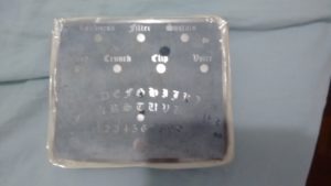 After some measurements I chose a Hammond 1590XX for the enclosure and the aluminium etching method. I used the same tone transfer method as used for the PCB, but I ended up using caustic soda instead of ferric chloride. I had some bleeding on the edges because I used tape to mask and some bleeding where the toner didn’t transferred properly, maybe next time I will seal everything with nail polish and use ferric chloride instead.
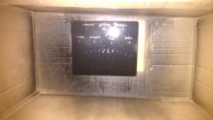 With the corrosion done, I sanded everything, painted the bas-relief with black spray, sanded again and applied varnish. I drilled it with my power drill, using one spade bit to start all holes(just the tip) and then used a step cone drill bit to the right size.
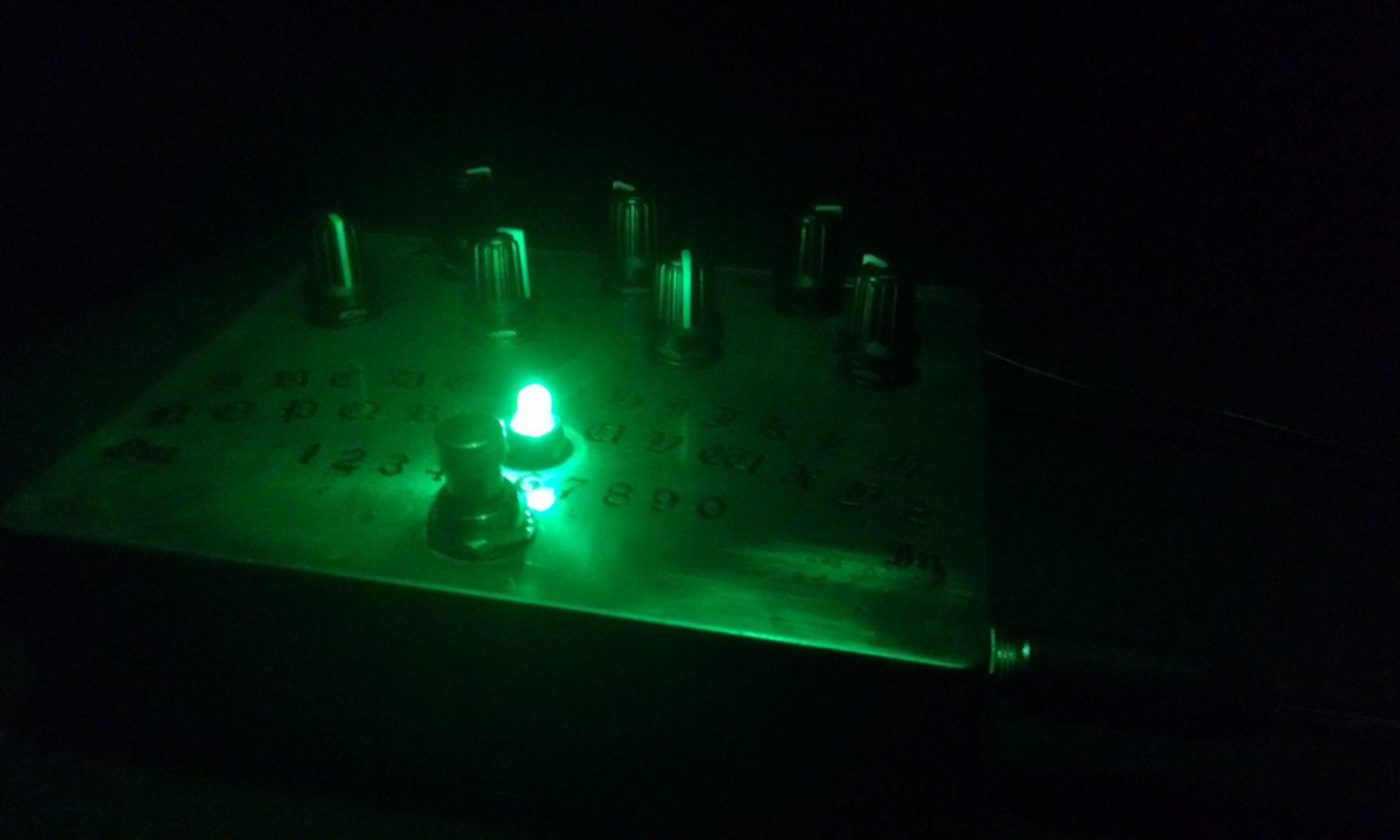
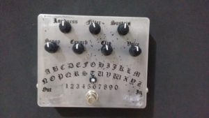
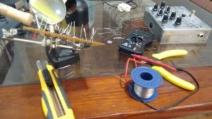 Nothing new with the PCB and Pedal assembly. I chosea super bright green LED as status indicator. It givesnice touchto the pedal, but ruined the video.
To the video I just downloaded some bass DI tracks over the internet and reamped them using the pedal.
Conclusion:
 It was a long and complex project for me. If I had the opportunity to redo anything today I would test the aluminium etching on a small scale first. The Eagle CAD part was tiring, but insightful. As for the video the LED ruined it, but I was so tired and wanted to publish something, so I didn’t record another take.
You can download the used Eagle files, ready to transfer pcb layout and partlist on my GitHub repository.